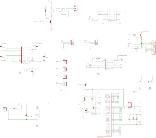
I finished doing the circuit diagram for my thermostat. Screenshot below:
Full schematic here (for Eagle 5.6).
I eventually chose Atmega16 for my CPU. It has enough memory and processing power for my needs (at least I hope so). Power is supplied from +5V 1.2A switching-mode power supply connected to SV3. Such power supply is noisy so to stabilize input voltage I use C1 and C12 capacitors (one tantalum 10uF and one simple ceramic 100nF). Q2 crystal together with C10 and C11 caps are used to generate clock signal and SV1 is used to program Atmega in ISP mode.
On the diagram there are two ICs, which perform the functions needed by a thermostat. IC1 is DS1307, a Real-Time Clock chip. It will be used to keep track of the time flow. The other IC is DS1721, a Digital Thermometer. It will be used to monitor the temperature in the room. Both chips communicate with Atmega16 by TWI (Two-Wire Interface).
Jumpers JP3 to JP6 are necessary to connect buttons. I will put buttons on the separate board, to make it easier to attach them to the casing. JP2 is used to connect standard 2x16 LCD with Hitachi HD44780 controller. Buttons and LCD Display together form user interface of the thermostat.
I added MAX3232 to the schematic. I don’t plan to use it now, but it’s very easy to implement some basic communication in RS232 standard, so it might come in handy in the future. I also added SV2 jumper for 1-wire, so I’ll be able to plug in additional digital thermometer later (DS1820).
Finally there is K1 - electromechanical relay. It is the only output of my thermostat, and it will be used to control the boiler. T1 transistor is protected against voltage spikes by D2 diode.